Estimate the population covered by LTE cells

In this tutorial we are going to estimate and analyze the population that is covered by LTE cells from the telecommunications infrastructure. In order to do that we are going to jointly analyze data with the location of the different LTE cells worldwide and a dataset of spatial features such as population, other demographic variables, urbanity level, etc. We will start by using CARTO Workflows to create a multi-step analysis to merge both sources of data, and we will then use CARTO Builder to create an interactive dashboard to further explore the data and generate insights.
In this tutorial we are going to use the following tables available in the “demo data” dataset of your CARTO Data Warehouse connection:
cell_towers_worldwide
usa_states_boundaries
derived_spatialfeatures_usa_h3res8_v1_yearly_v2
Let's get to it!
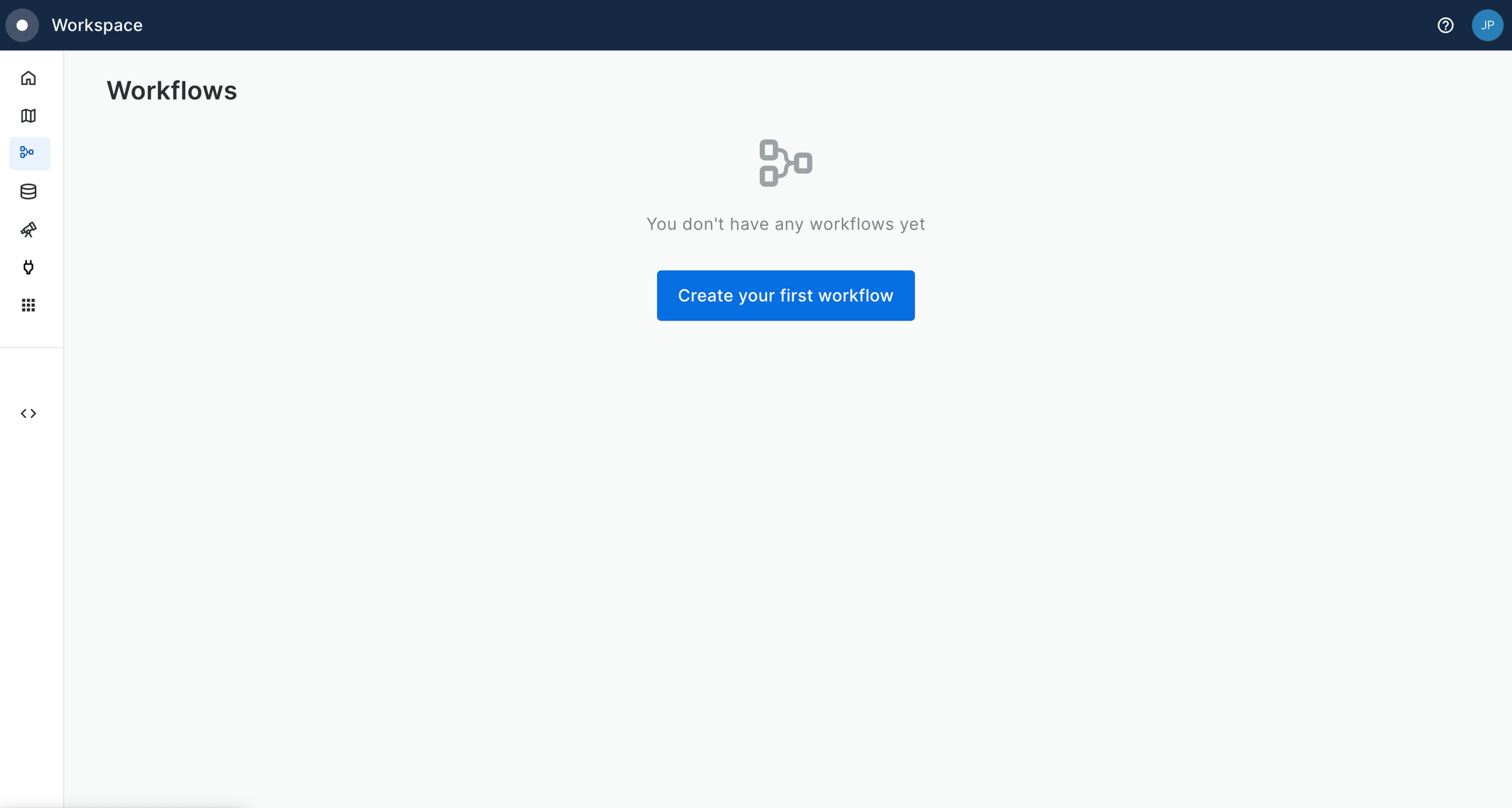
In your CARTO Workspace under the Workflows tab, create a new workflow.
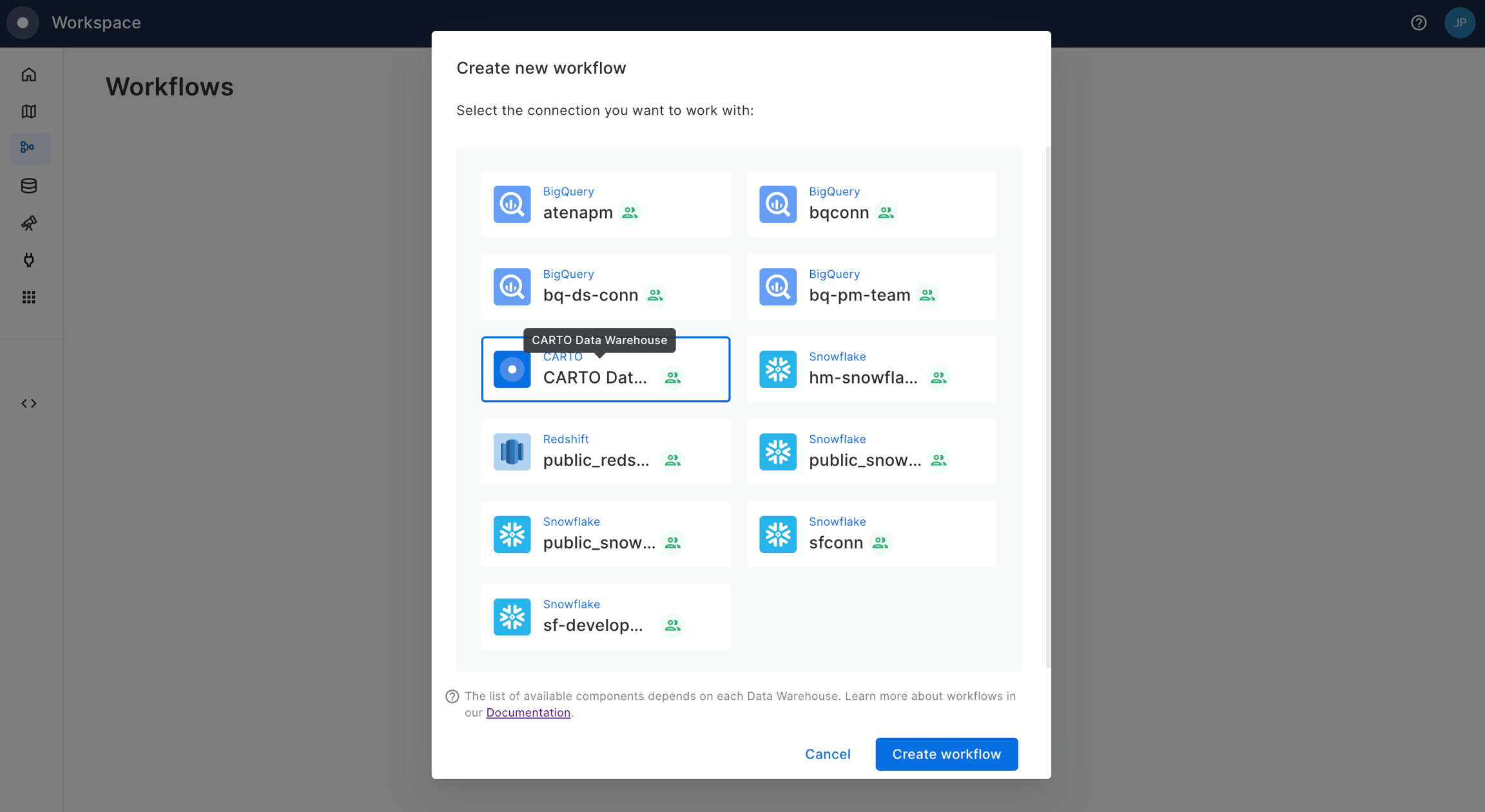
Select the data warehouse where you have the data accessible. We'll be using the CARTO Data Warehouse, which should be available to all users.
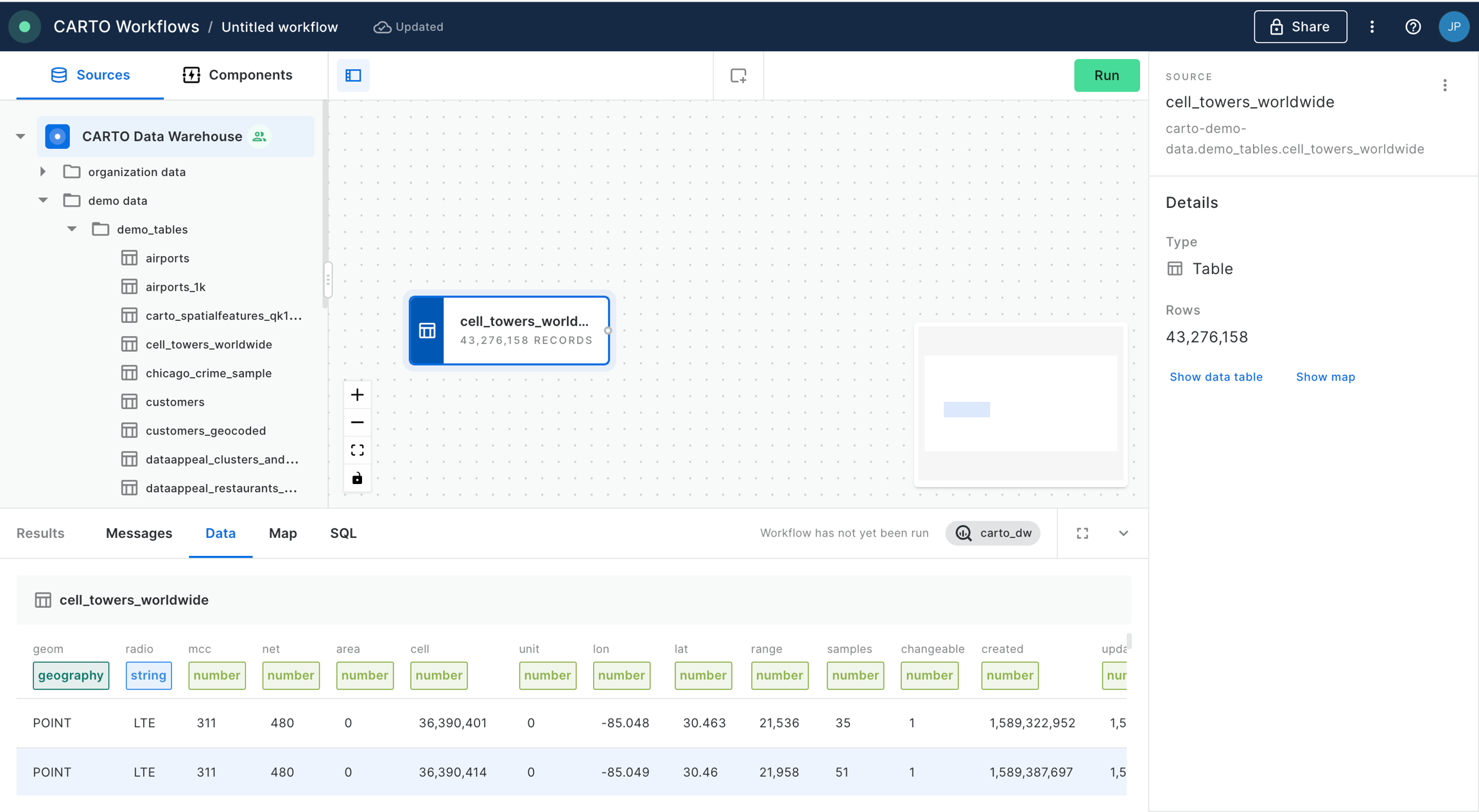
Navigate the data sources panel to locate your table, and drag it onto the canvas. In this example we will be using the
cell_towers_worldwidetable available in demo data. You should be able to preview the data both in tabular and map format.
If your CARTO account has been provisioned on a cloud region outside the US (e.g., Europe-West, Asia-Northeast), you will find the demo data under CARTO's Data Warehouse region (US). For more details, check out the CARTO Data Warehouse documentation.
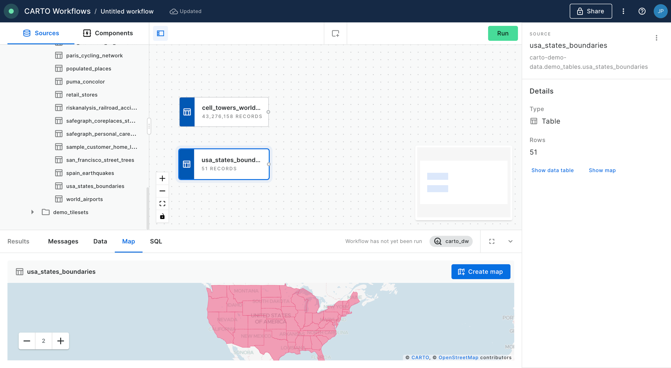
We also add the table
usa_states_boundariesinto the workflows canvas; this table is also available in demo data.
First, we want to select only the boundary of the US State which we are interested in for this analysis; in this example we will be using Massachusetts. In order to filter the
usa_states_boundariestable we will be using the component “Simple Filter”, which we should now also drag and drop into the canvas and connect the data source to the component node.
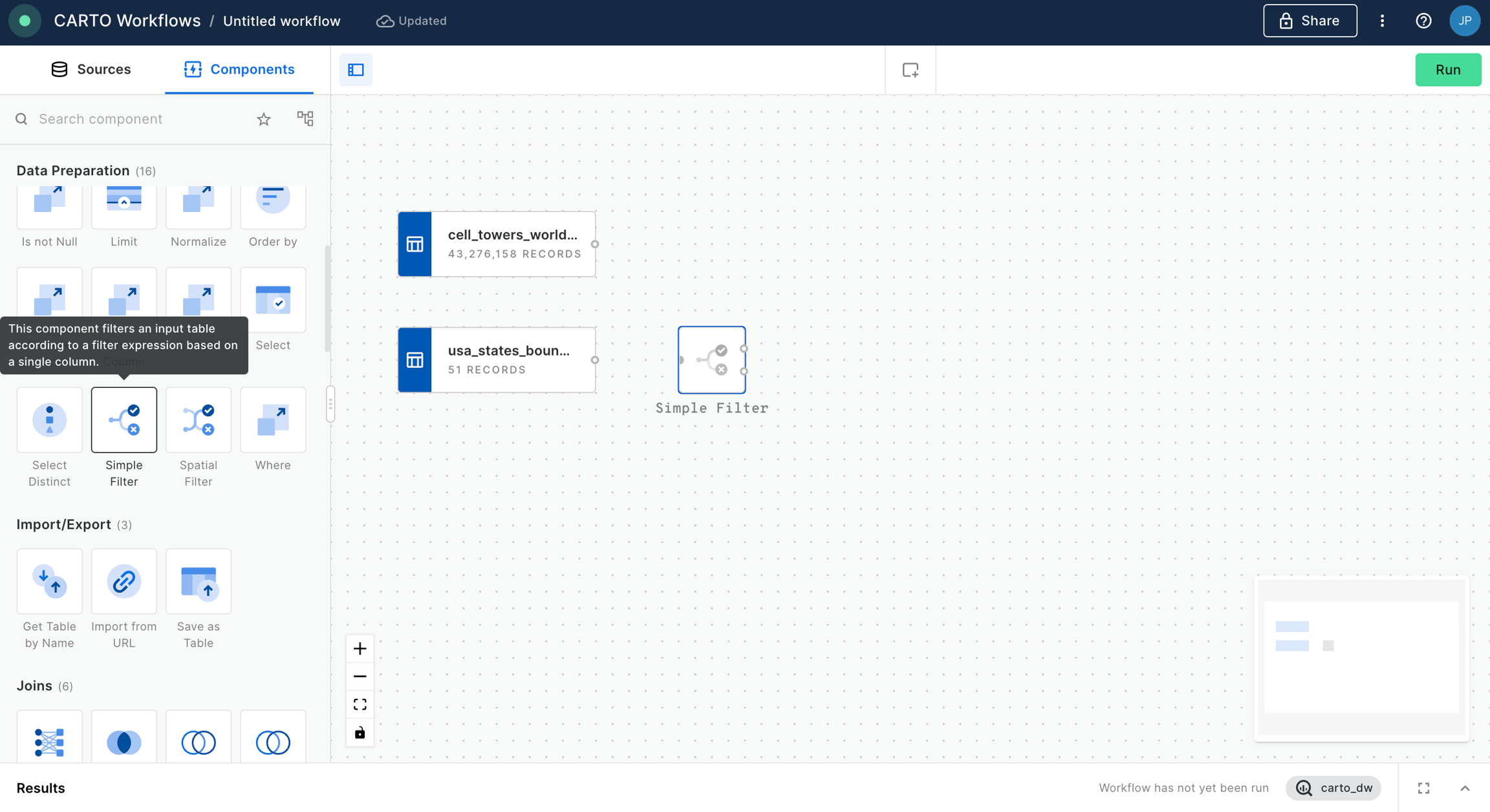
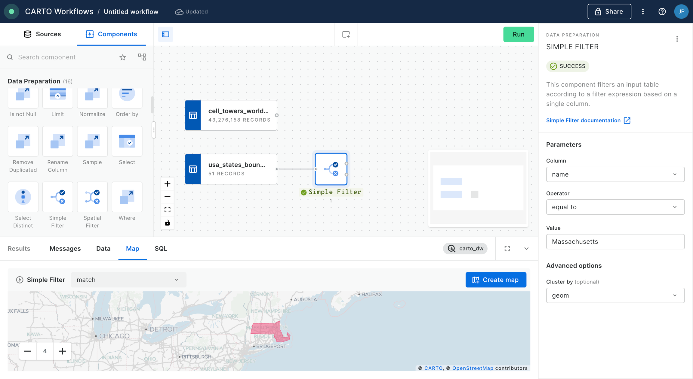
We configure the “Simple Filter” node in order to keep the column “name” when it is “equal to” Massachusetts. We click “Run”.
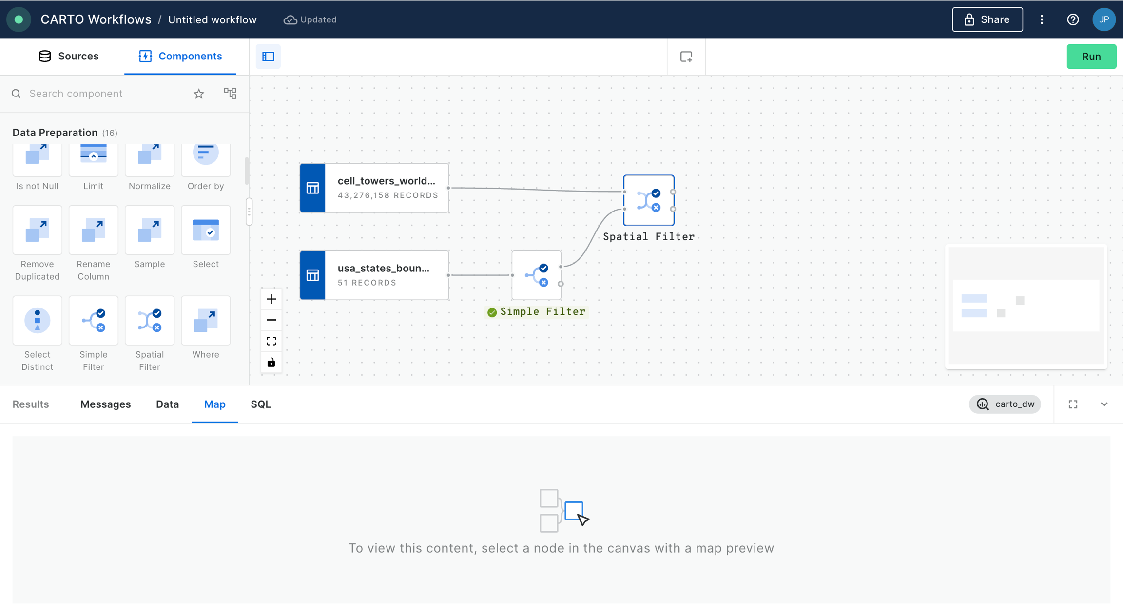
We will now filter the data in the
cell_towers_worldwidein order to keep only the cell towers that fall within the boundary of the state of Massachusetts. In order to do that, we will add a “Spatial Filter” component and we will connect as inputs the data source and the output of the previous “Simple Filter” with the result that has matched with our filter (the boundary of Massachusetts).
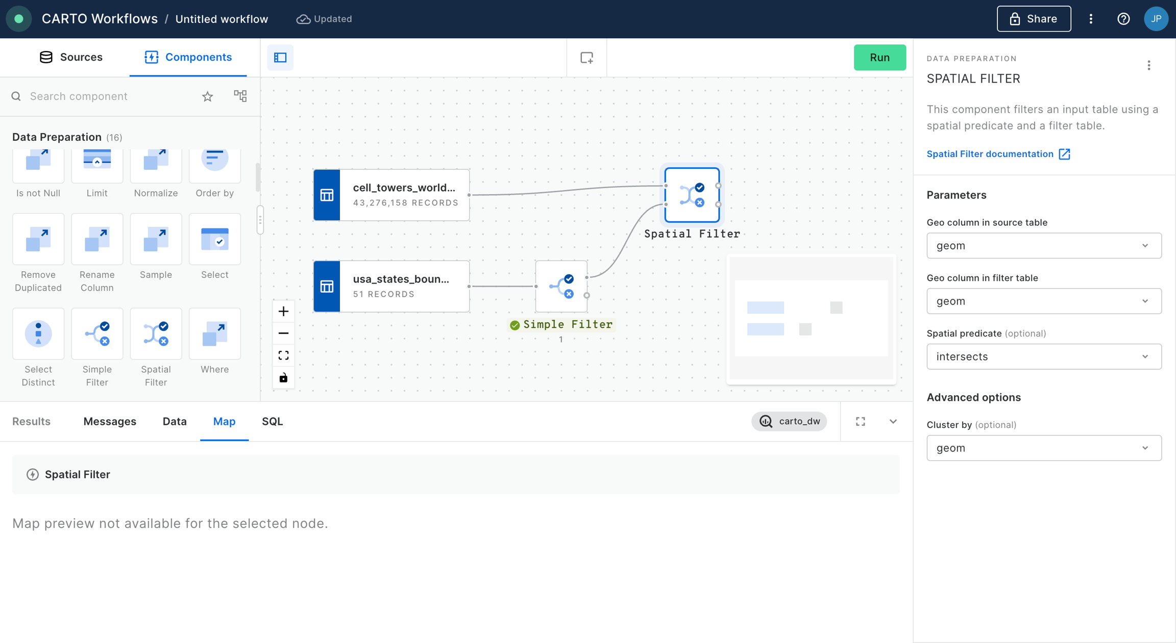
We configure the “Spatial Filter” with the “intersects” predicate, and identify the “geom” column for both inputs. We click “Run”.
We can see now in the output of the “Spatial Filter” node that we have filtered the cell towers located within the state of Massachusetts.
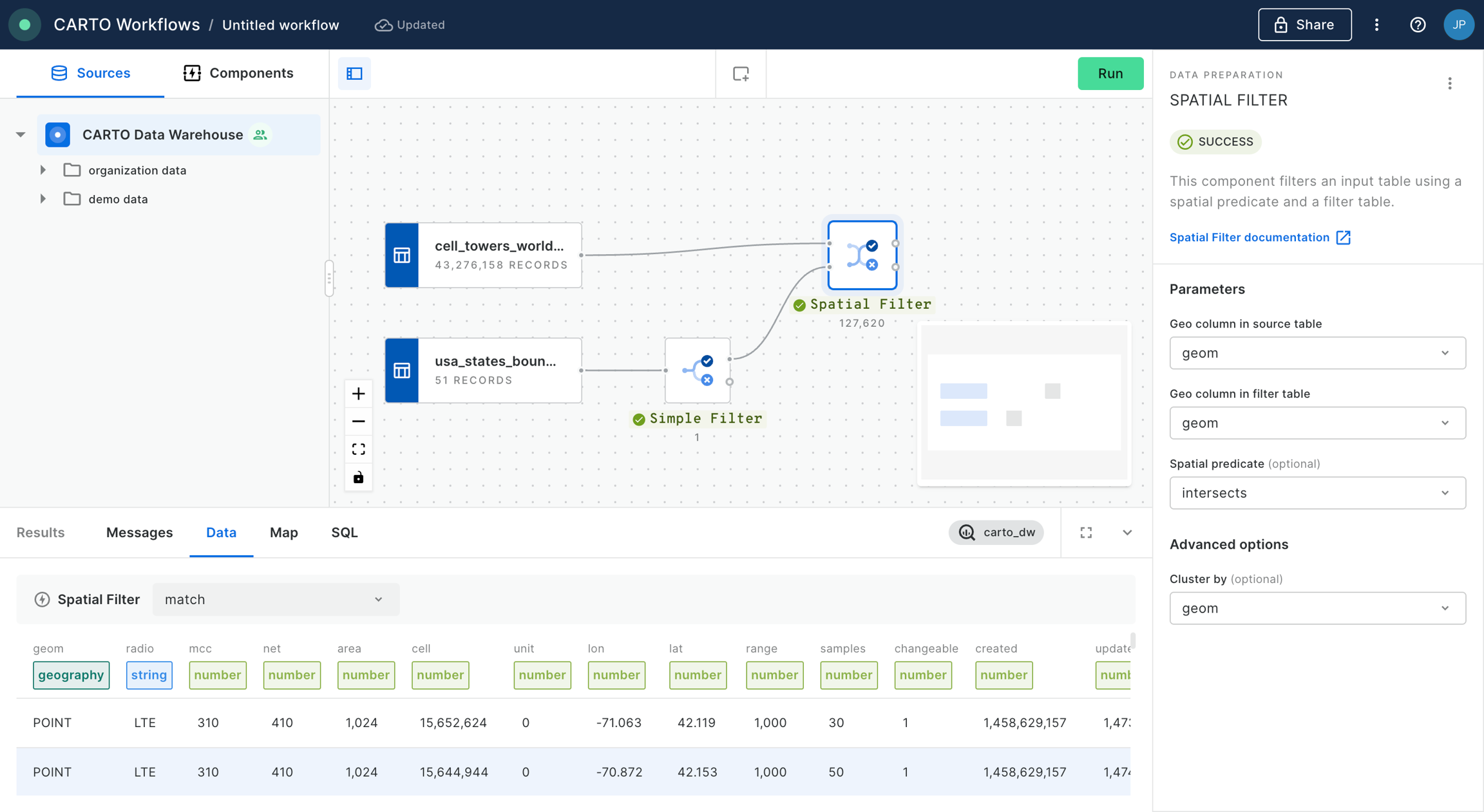
We are now going to create a buffer around each of the cell towers. For that, we add the “ST Buffer” component into the canvas. We configure that node to generate buffers of 300 meters. We click “Run”.
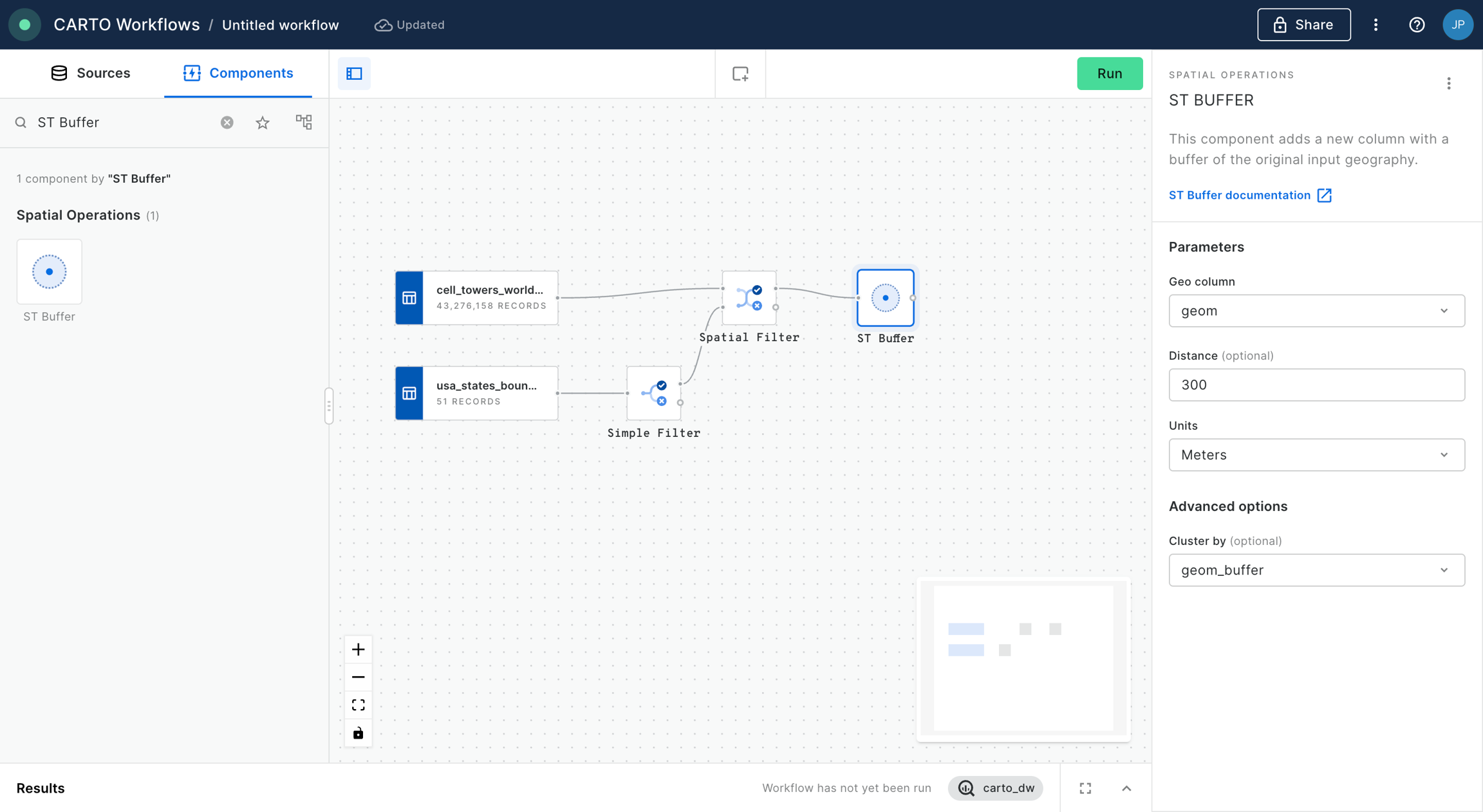
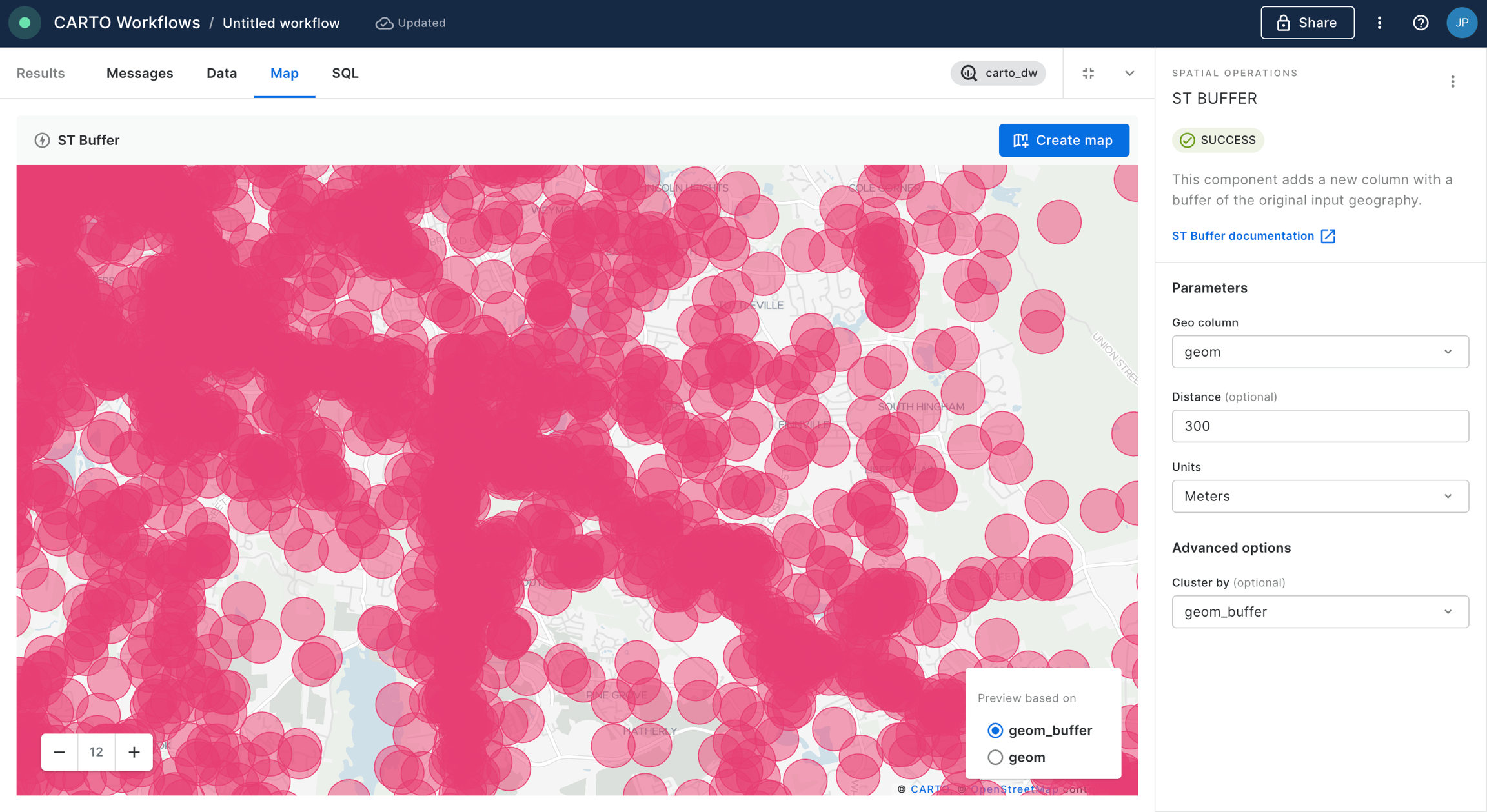
You can preview the result of the analysis by clicking on the last node of the “ST Buffer” and preview the result on map.
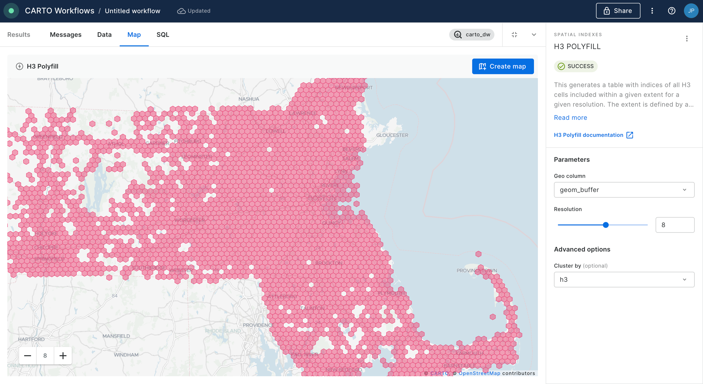
Now, we are going to polyfill the different buffers with H3 cells. For that we add the component “H3 Polyfill” and we configure the node to be based on cells of resolution 8, we select the geom_buffer as the geometry data to be polyfilled and we cluster the output based on the H3 indices. We then click “Run” again.
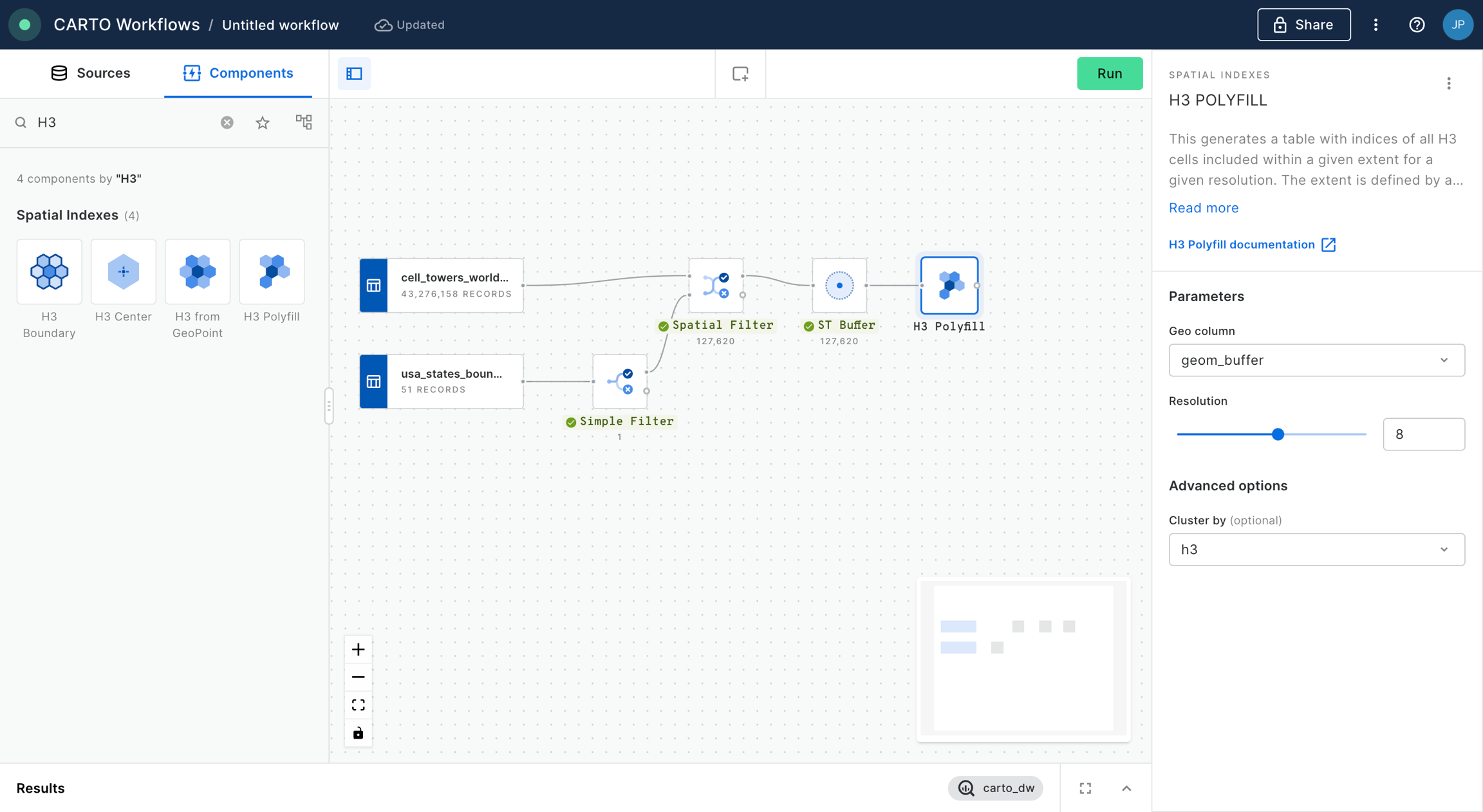
Check how now the data has been converted into an H3 grid.
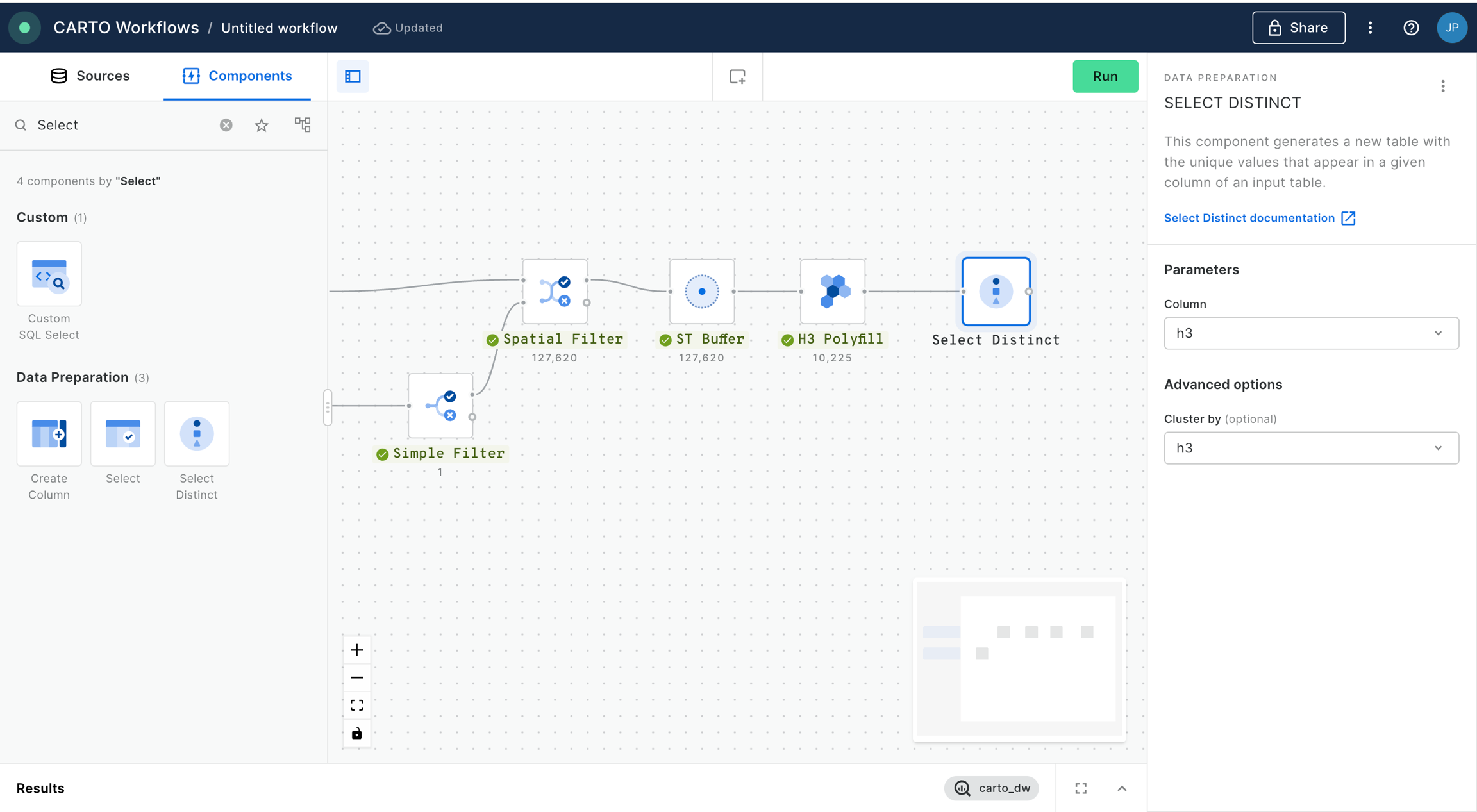
We now will add a “Select Distinct” component in order to keep in our table only one record per H3 cell, and to remove those resulting from overlaps between the different buffers. In the node configuration we select the column “h3” to filter the unique values of the H3 cells present in the table.
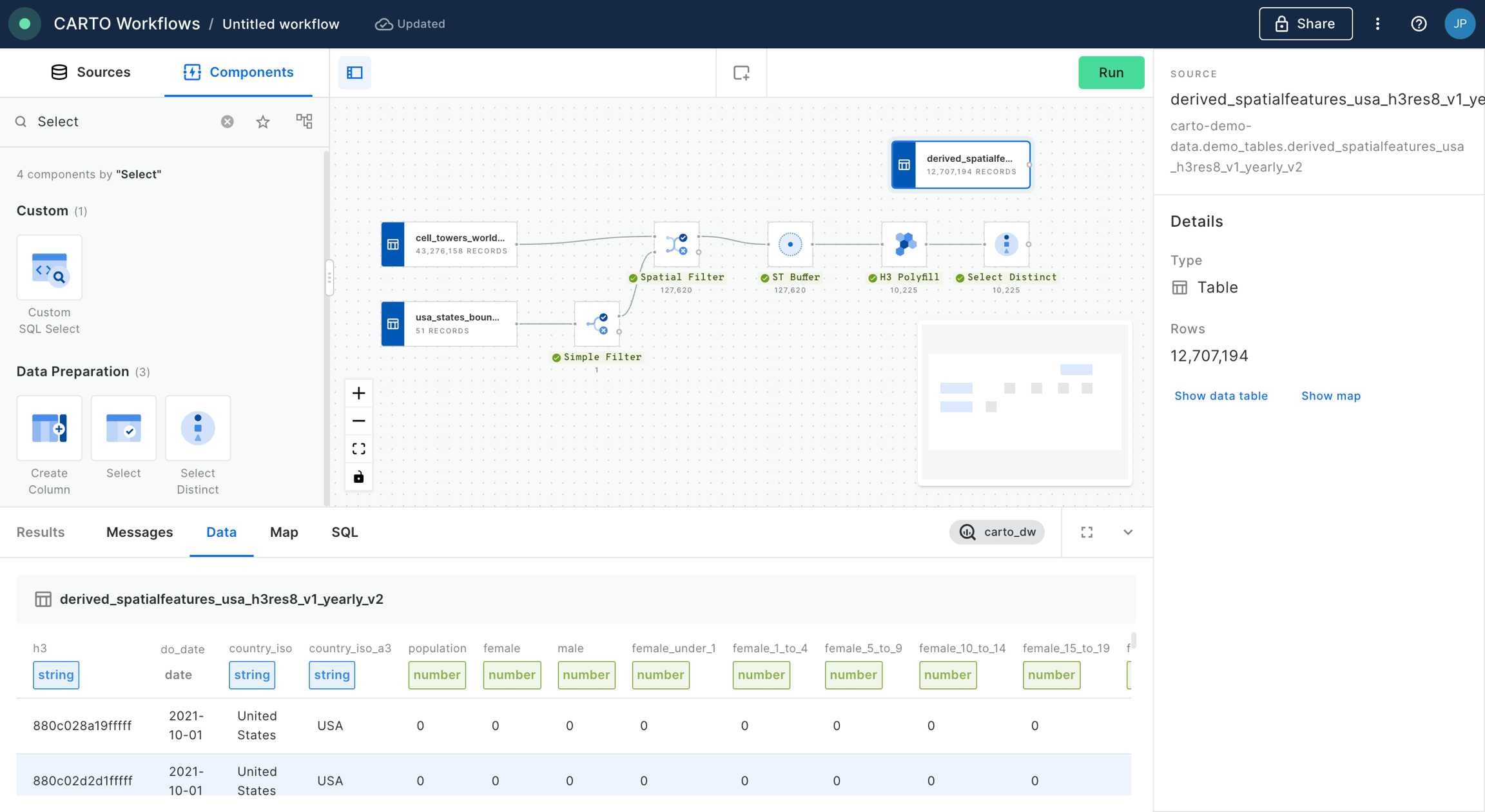
We now add a new data source to the canvas, we select the table
derived_spatialfeatures_usa_h3res8_v1_yearly_v2from demo data.
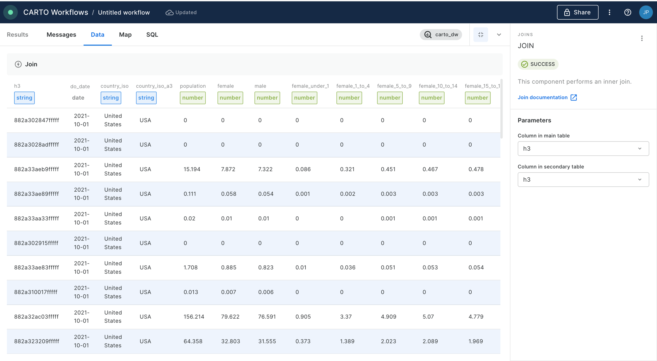
We add a “Join” component in order to perform an inner join between the data from the Spatial Features dataset and the output of our workflow so far, based on the h3 indices present in both tables. Click “Run”.
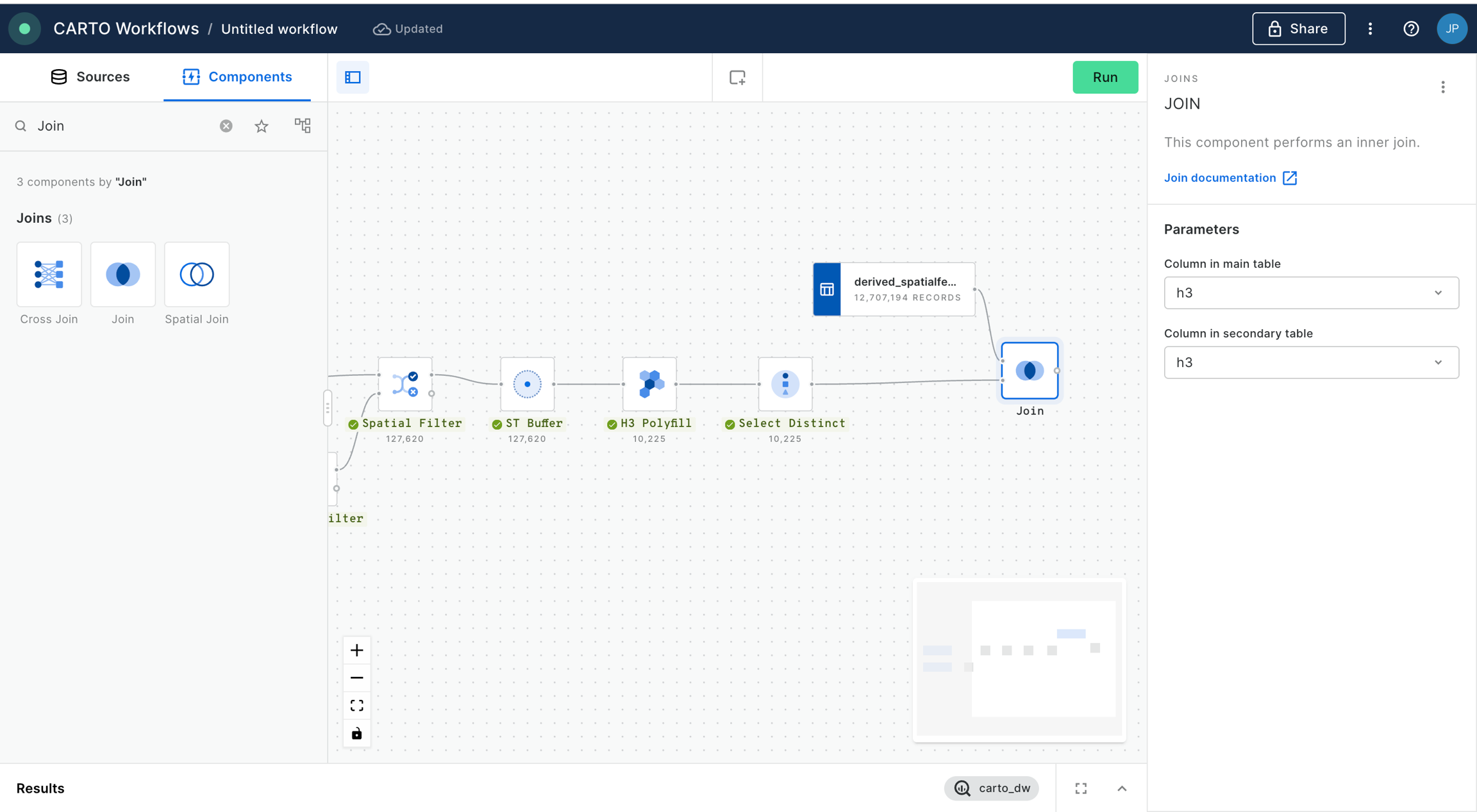
Please check now how the output of the workflow contains the data from the spatial features table only in those cells where we know there is LTE coverage.
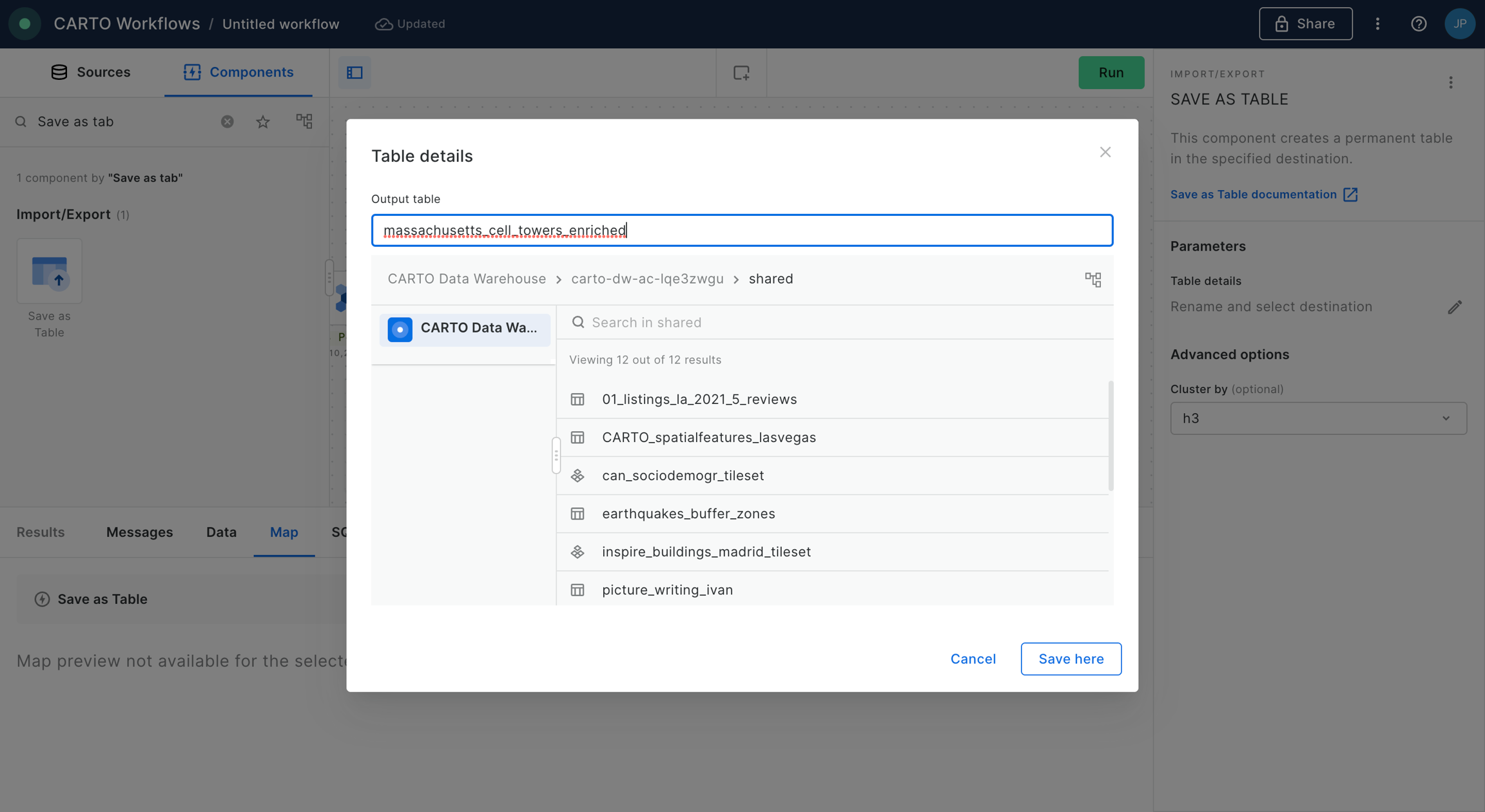
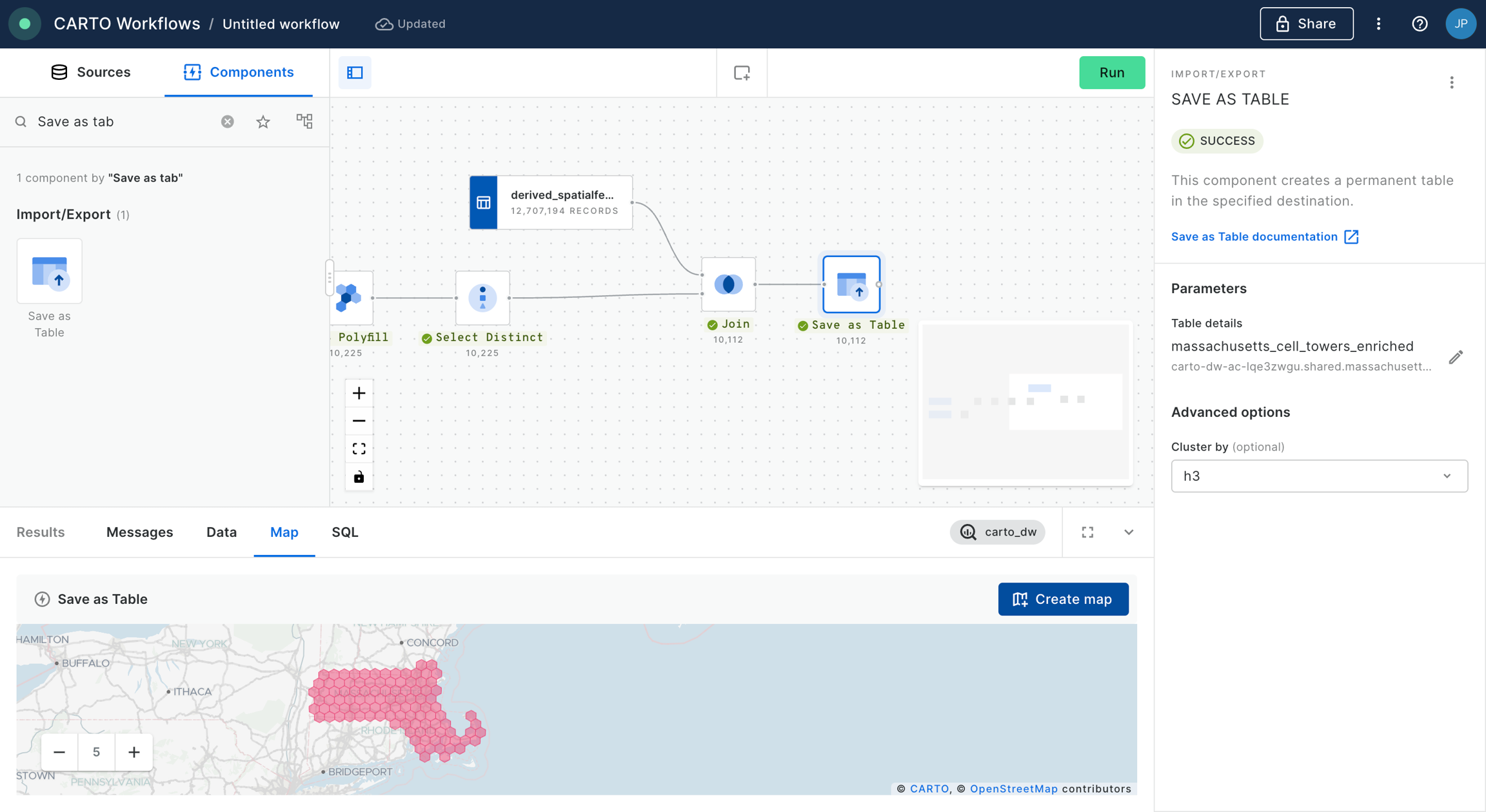
Finally, we are going to save the result of our workflow as a new table in our data warehouse. For that, we are going to add the component “Save as table” into the canvas and connect the output of the previous step where we performed the “Join” operation. In this example we are going to save the table in our CARTO Data Warehouse, in the dataset “shared” within “organization data”. We click “Run”.
Workflows also allows us to create maps in Builder in order to make interactive dashboards with any of our tables (i.e. saved or temporary) at any step of the workflow. In this case, select the “Save as table” component and from the “Map” preview in the Results section click on “Create map”. This will open Builder on a different tab in your browser with a map including your table as a data source.
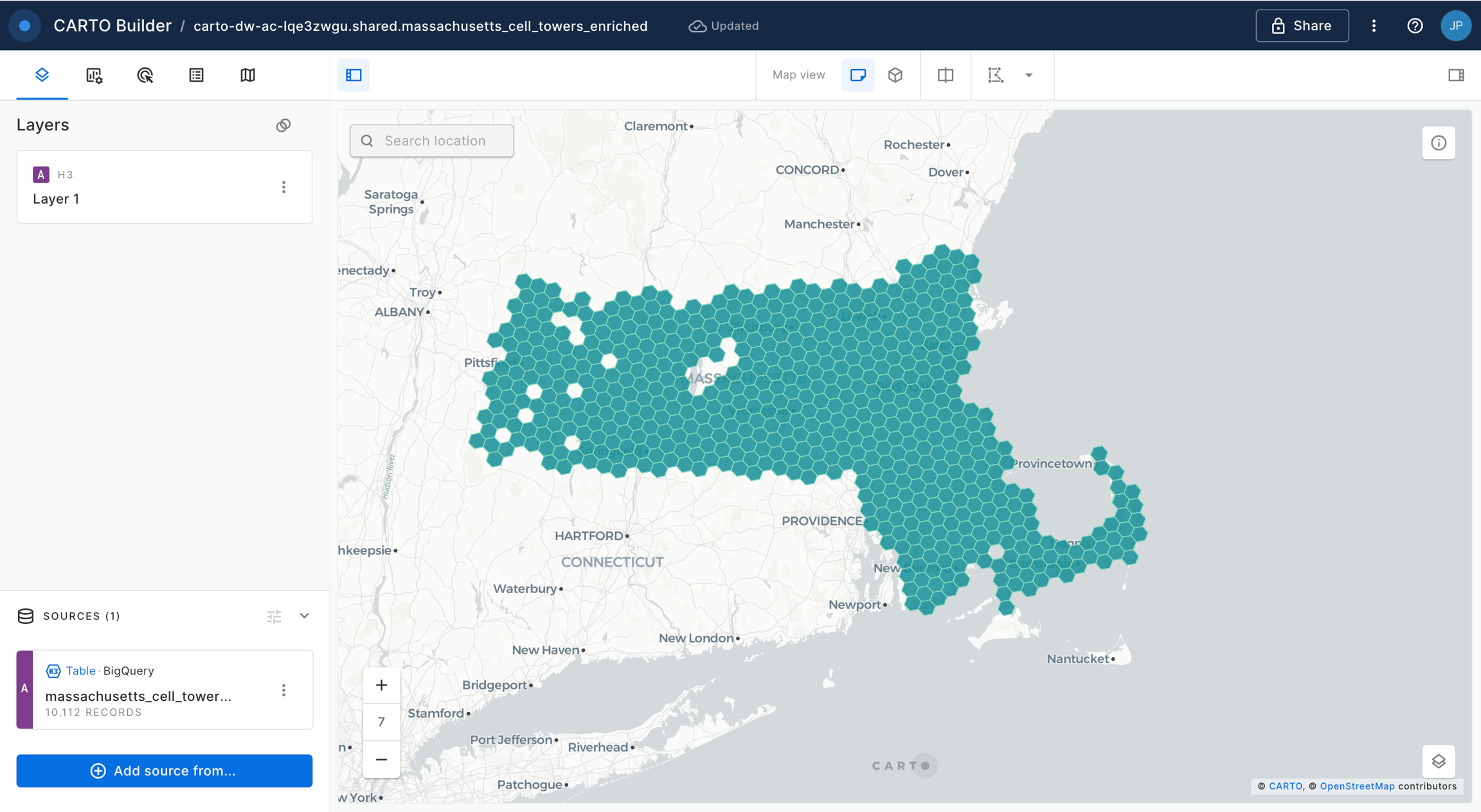
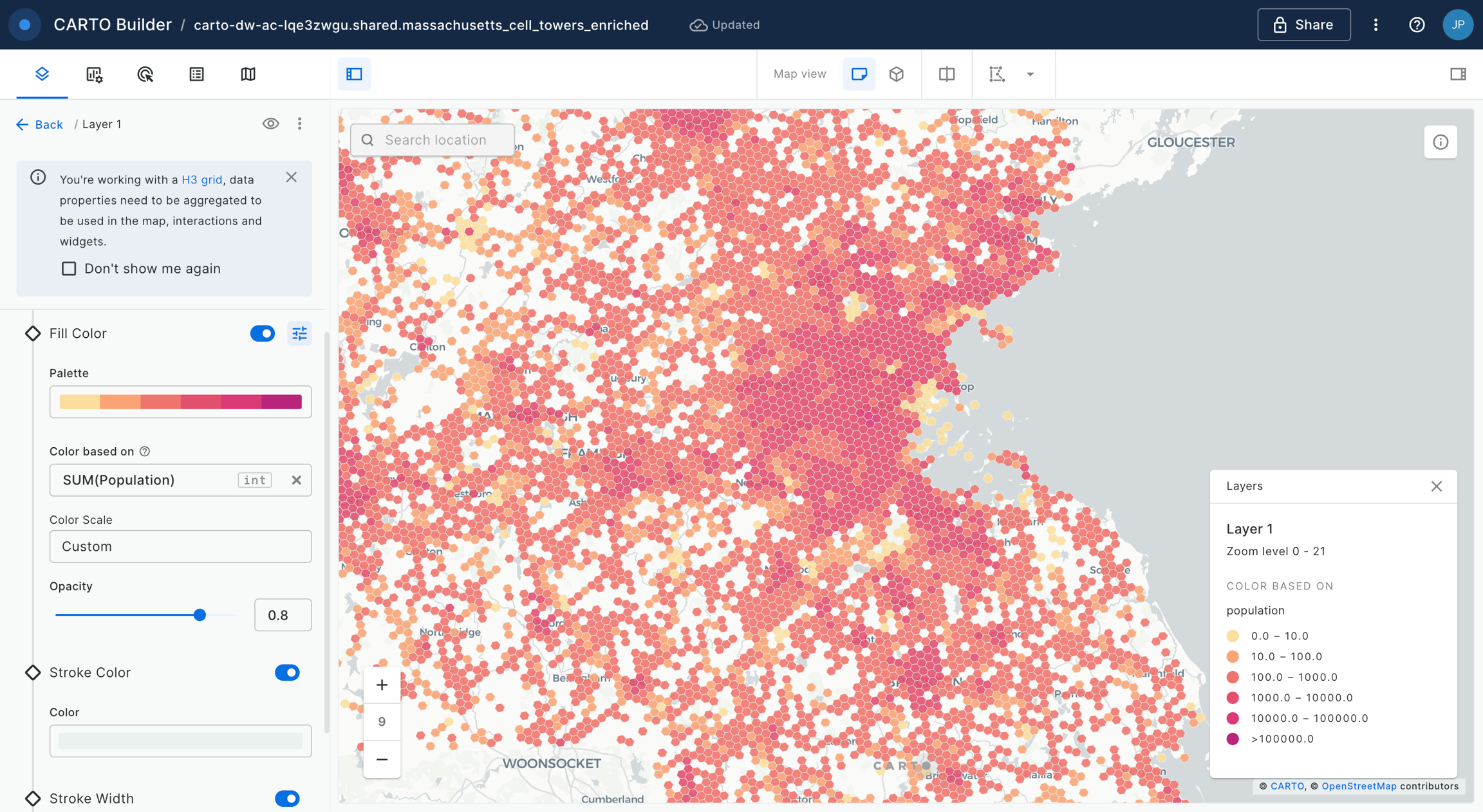
We can now style our layer based on one of the columns in the table, for example “Population”.
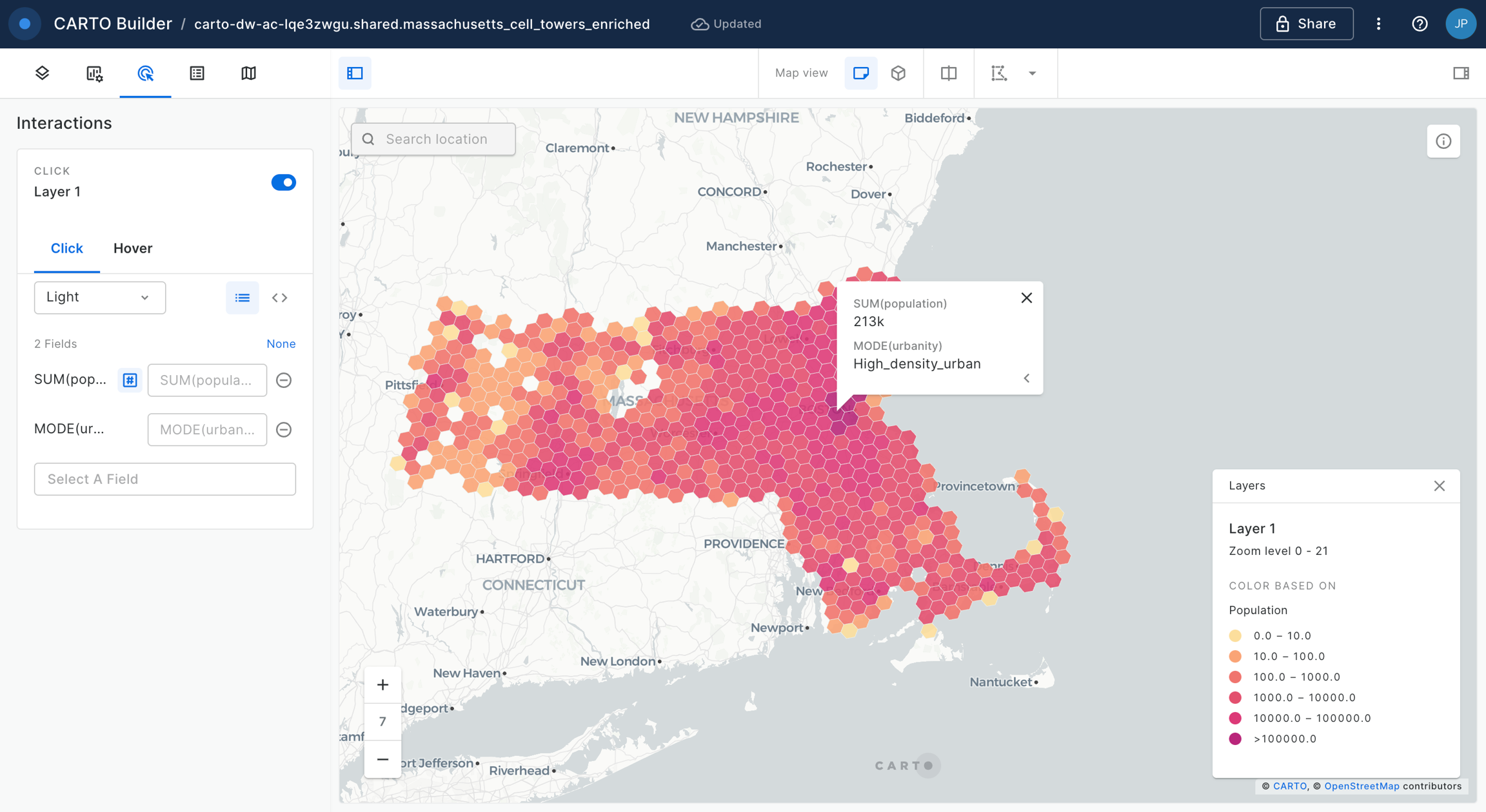
We can add “Interactions” to the map, so as to open pop-up windows when the user clicks or hovers over the H3 cells.
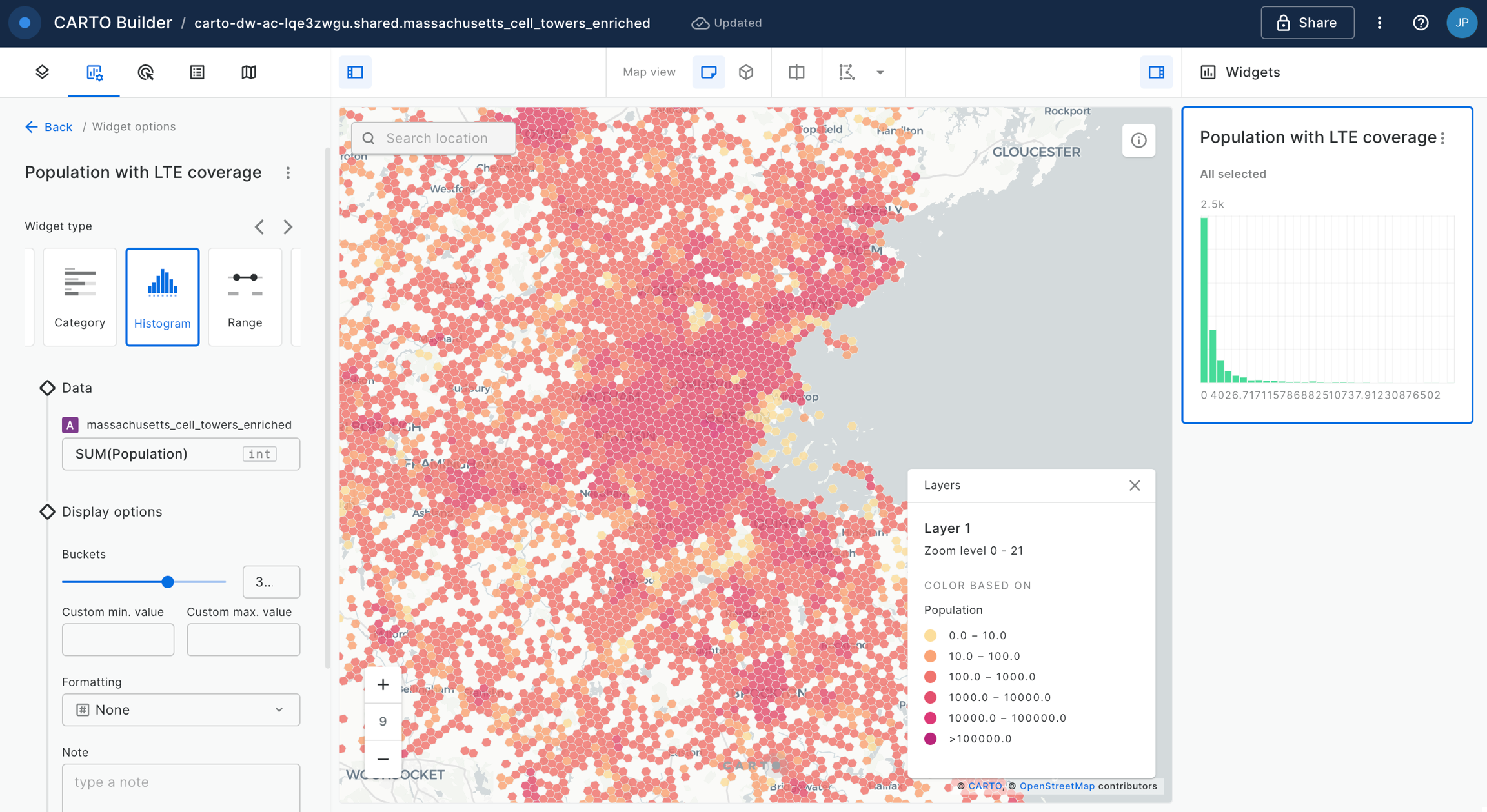
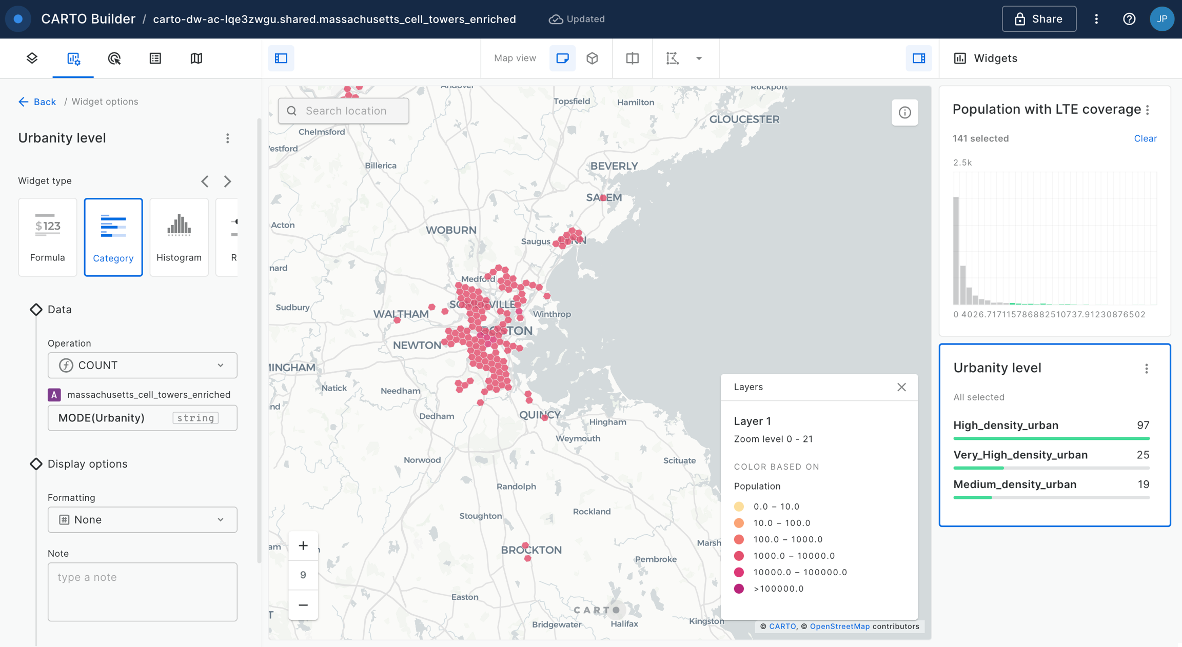
And we can add widgets in order to further explore and filter our data. For example we are going to add an Histogram widget based on the population column.
We add a second widget in order to filter the cells based on the dominant urbanity level; for that we use a Category widget.
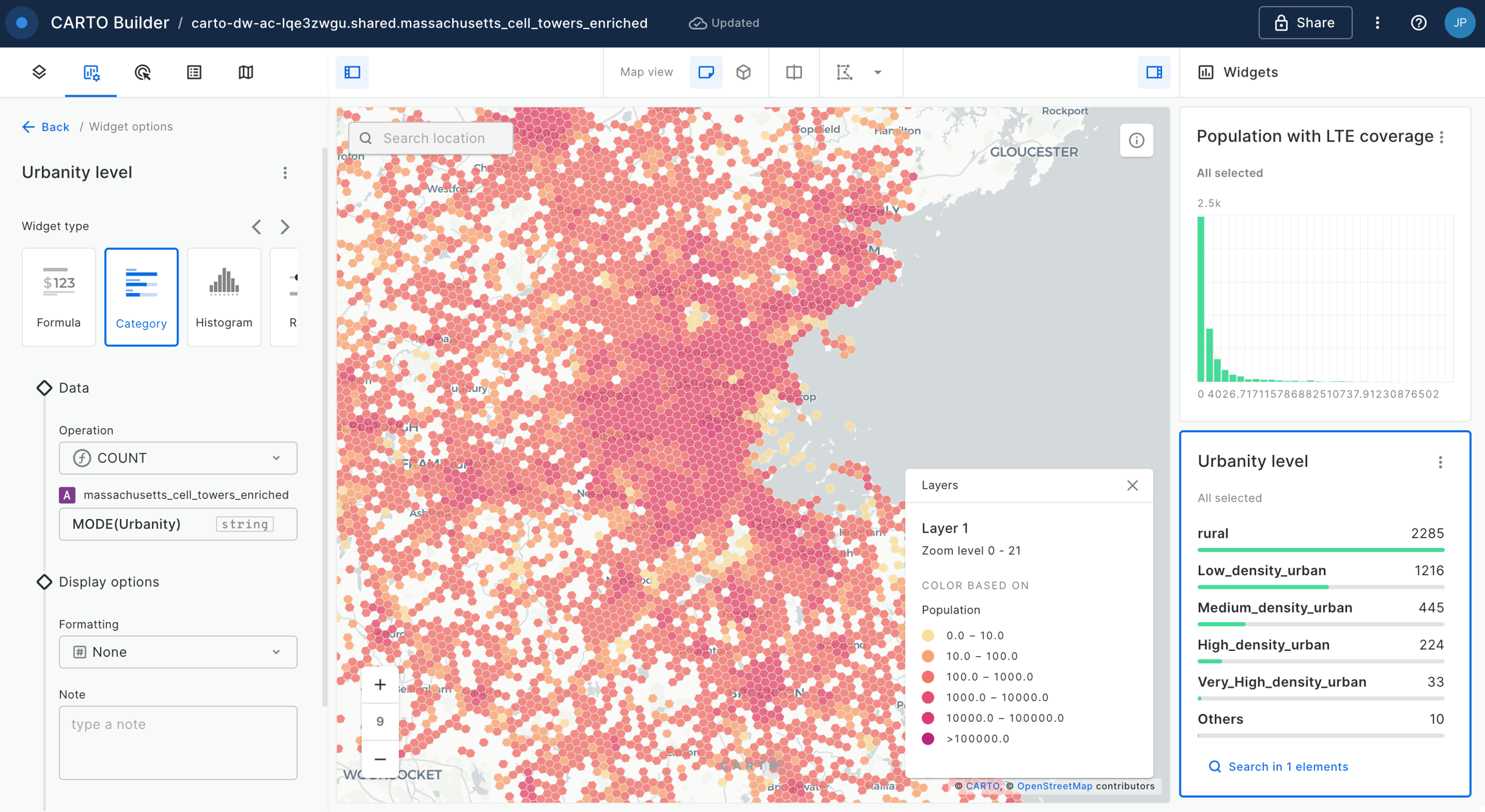
We can now start interacting with the map. Check how, for example, the area with more population covered by LTE cells is concentrated in the Boston area (which are mostly quite dense urban areas).
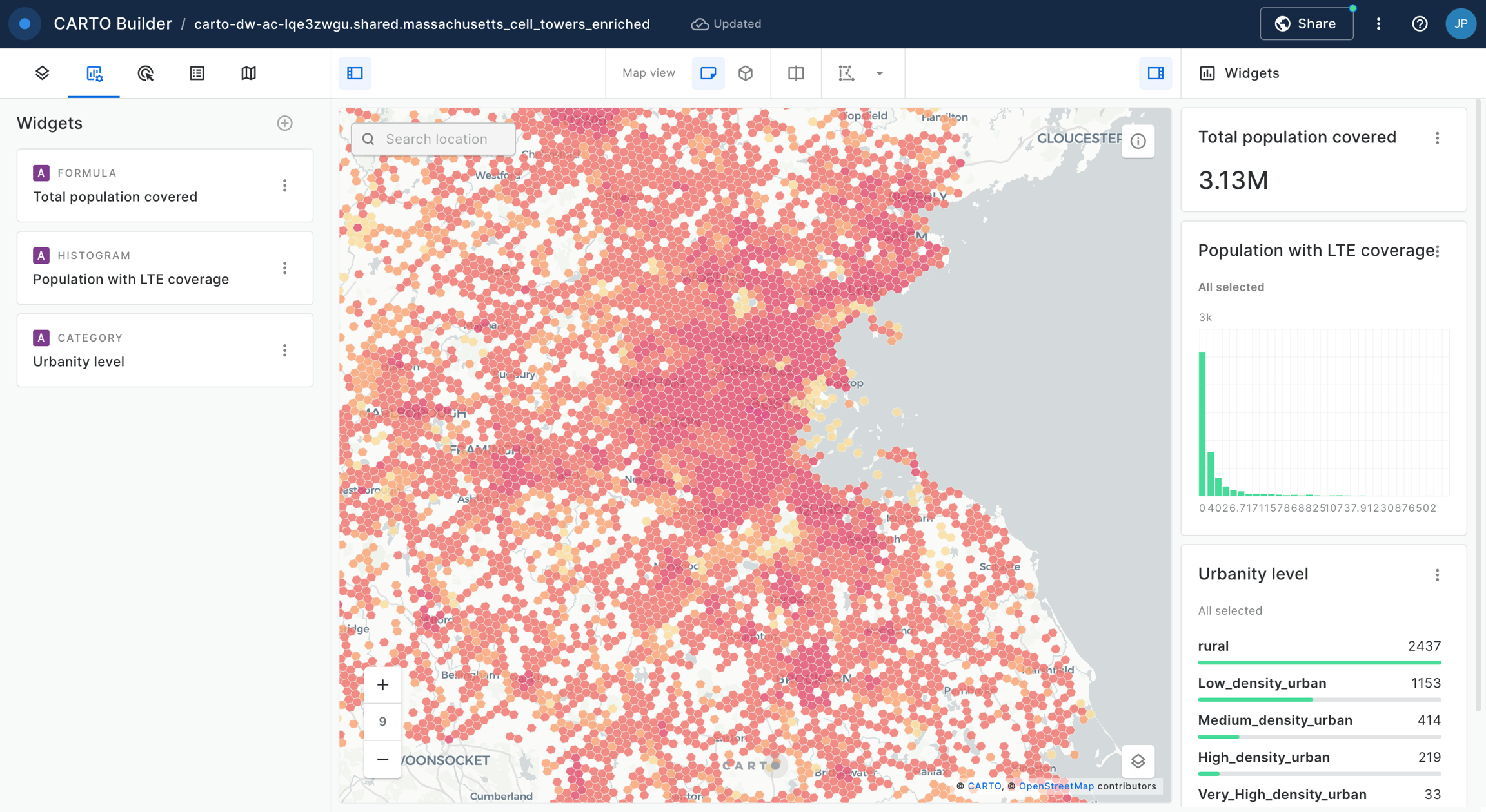
We add a final Formula widget to compute the total population covered (based on the data in the viewport of the map).
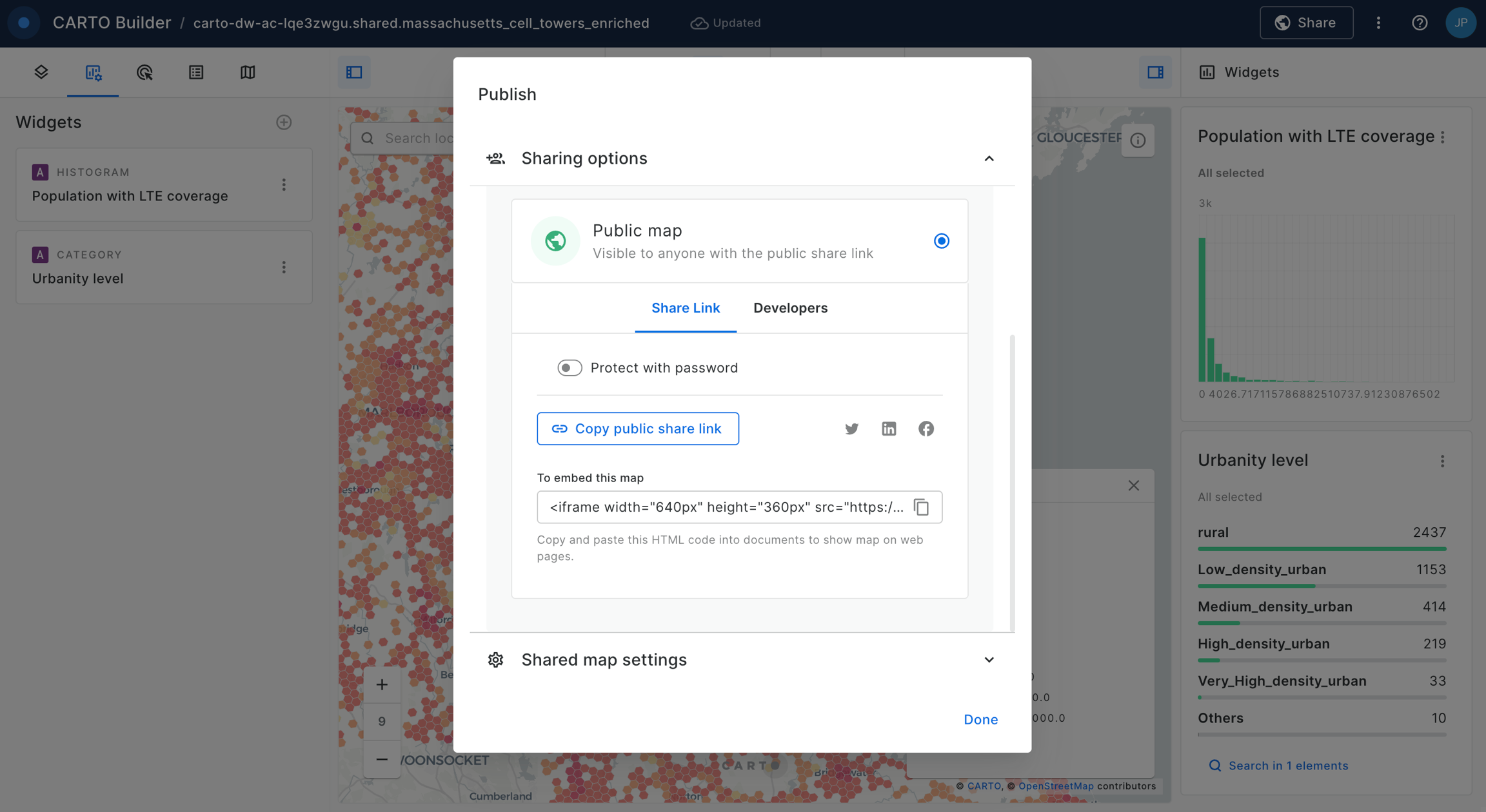
Finally we can share our map publicly or just with the rest of users within our CARTO organization account.
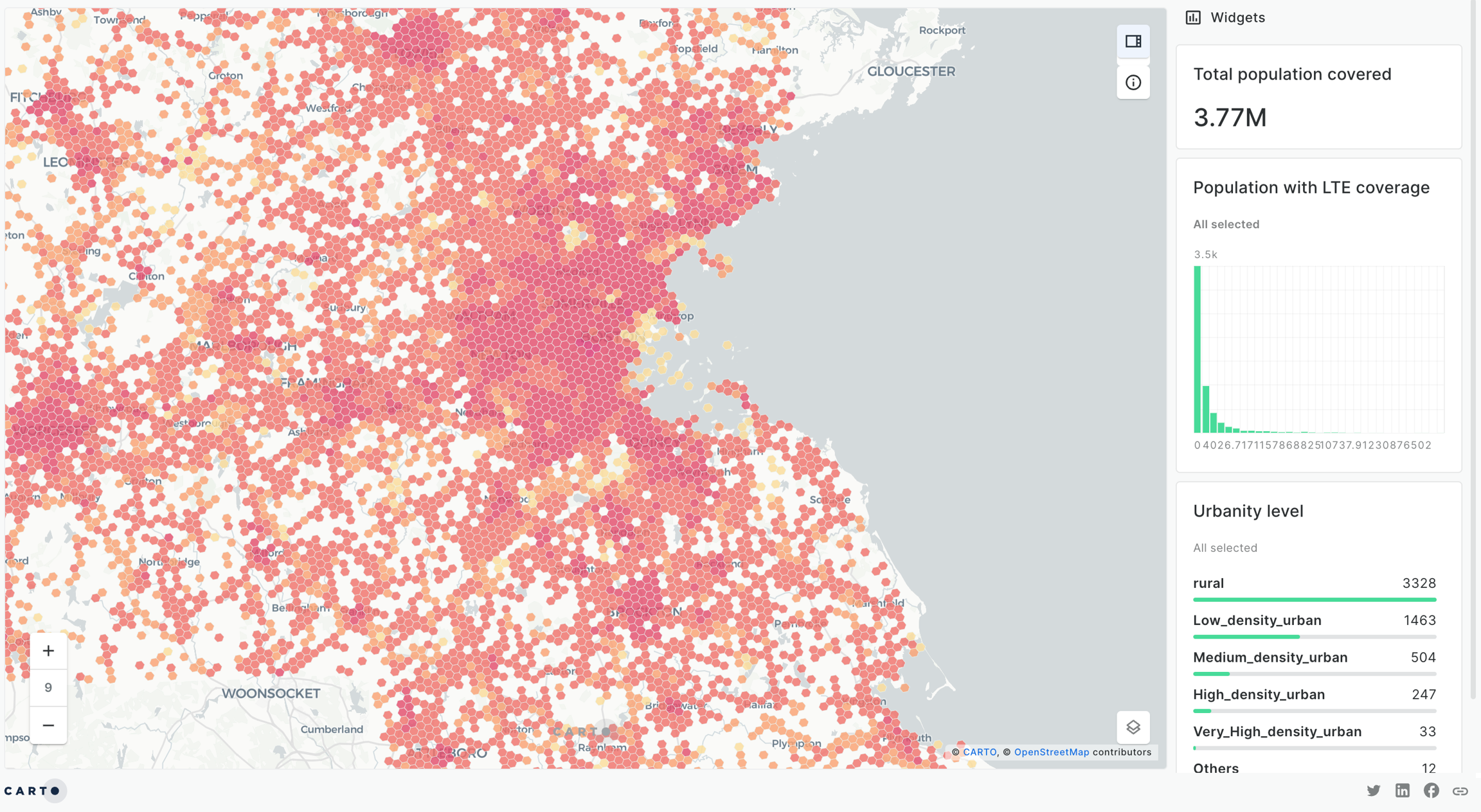
We are done! This is how or final map looks like:
And that's a final view on how our analysis workflow looks like:
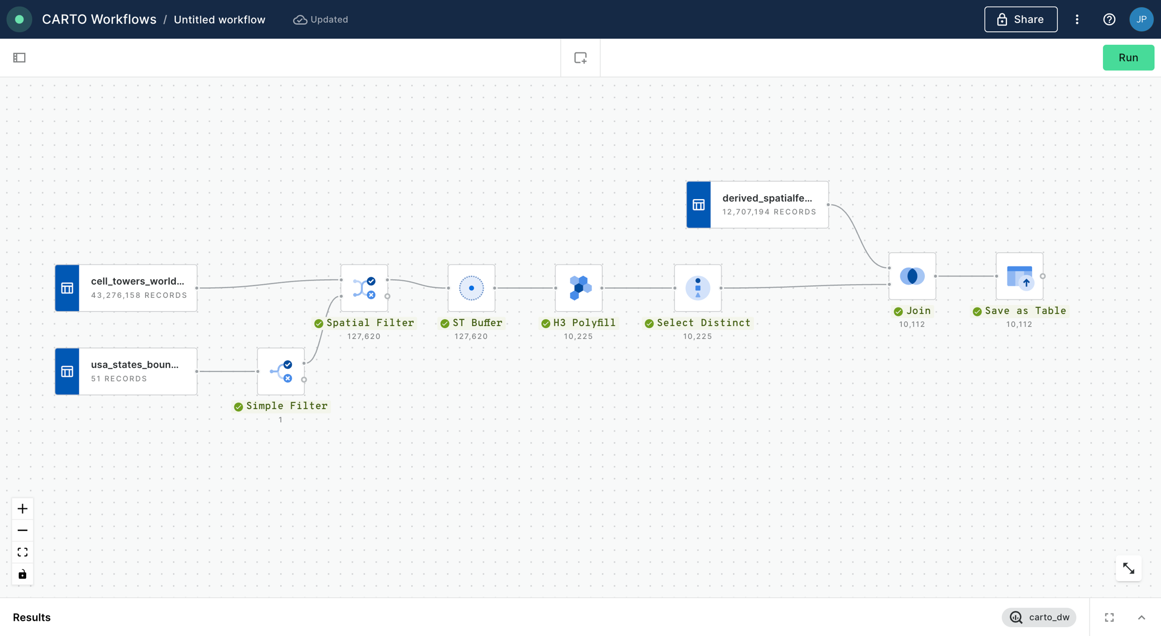
We hope you enjoyed this tutorial and note that you can easily replicate this analysis for any other US state or even other parts of the world.
Last updated
Was this helpful?

